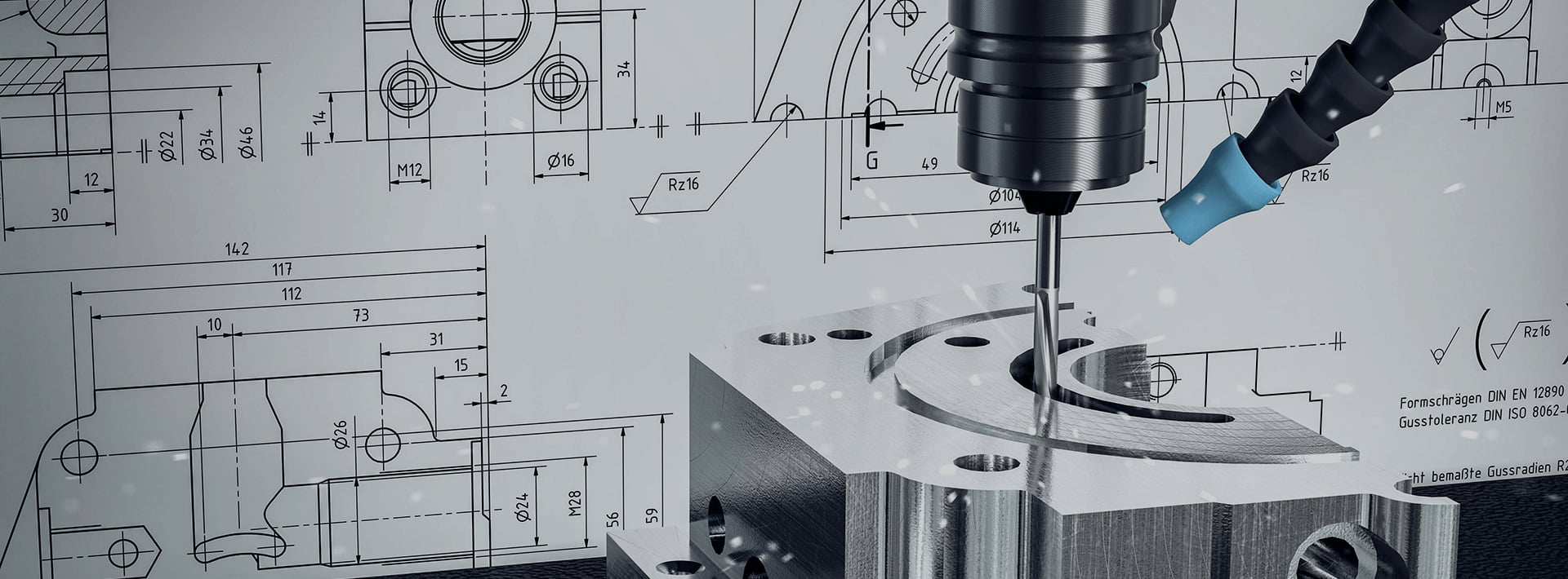


All You Need To Know Engineering Drawing And Its Elements
Engineering drawing is a graphical language used to communicate design ideas, specifications, and details of engineering components or systems. It serves as a universal tool for engineers, manufacturers, and designers to convey how a product should be made or assembled. Below are its key elements:
. Drawing Sheet & Format
- Sheet Sizes: Standardized sizes (e.g., A0 to A4) with specific dimensions to ensure consistency.
- Title Block: Located at the bottom-right corner, containing details like drawing title, part number, scale, date, author, and company logo.
- Borders & Margins: Defined edges to frame the drawing area, ensuring clarity and professionalism.
. Lines
Lines are the foundation of engineering drawings, with different types indicating specific features:
- Visible Lines: Thick, continuous lines showing the outline of visible parts.
- Hidden Lines: Dashed lines representing edges or features not visible from the current view.
- Centre Lines: Thin, long-short dashed lines marking the center of circles, cylinders, or symmetrical objects.
- Dimension Lines: Lines with arrows at both ends, used to specify sizes (e.g., length, diameter).
- Extension Lines: Thin lines extending from the object to connect with dimension lines.
- Cutting-Plane Lines: Thick lines (often with arrows) indicating where a section view is taken.
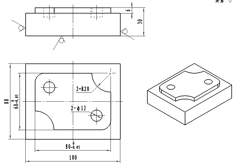
. Views
Engineering drawings use multiple views to fully describe an object (based on orthographic projection):
- Front View: The main view, showing the most important features.
- Top View: View from above, aligned with the front view.
- Side View: View from the right or left, aligned with the front view.
- Section Views: Show internal details by "cutting" the object along a plane (e.g., full section, half section).
- Isometric View: A 3D-like perspective to visualize the object's shape (not to scale for measurements).
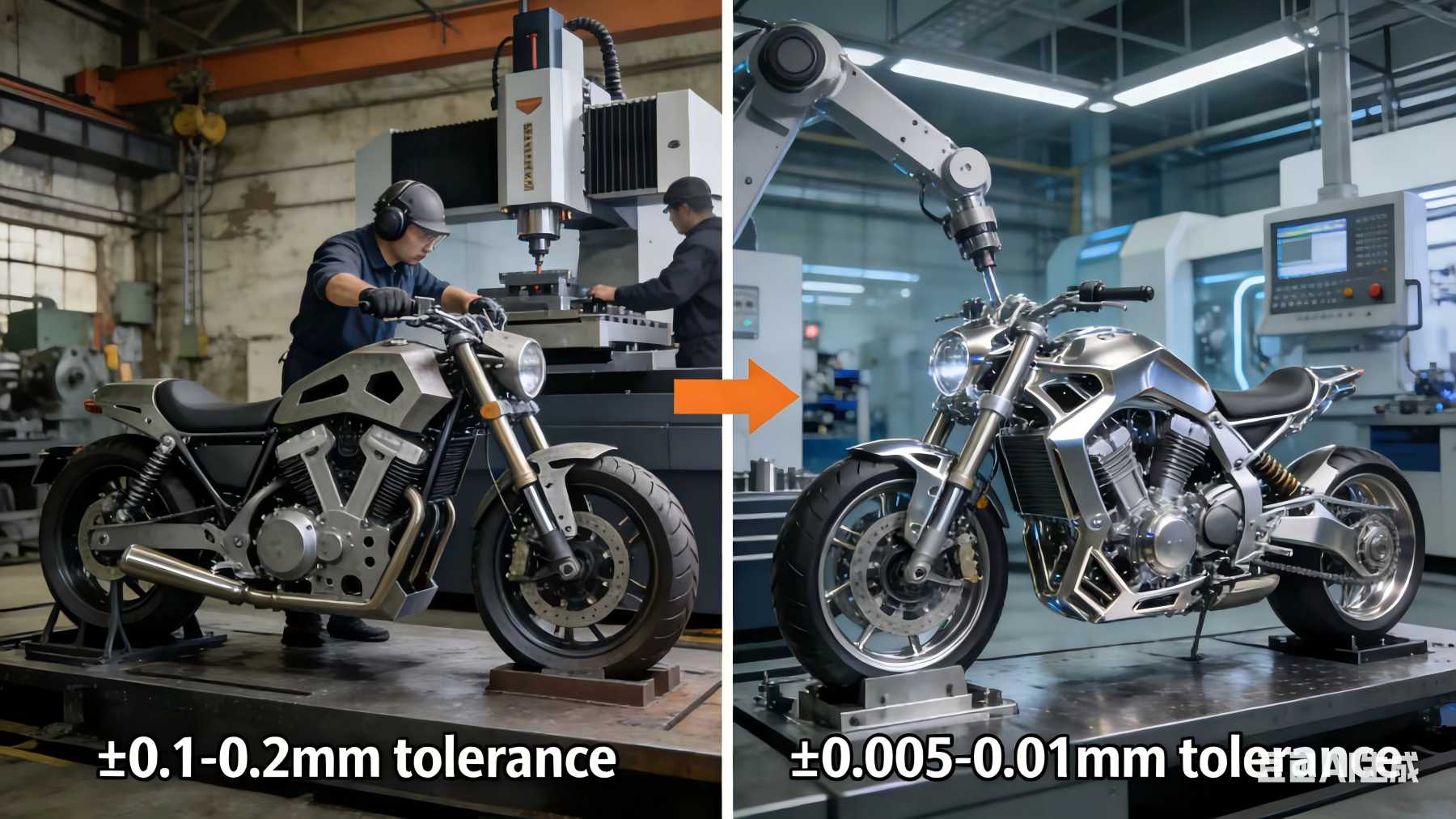
. Dimensions & Tolerances
- Dimensions: Numerical values (in mm, inches, etc.) specifying the size of features (e.g., "50mm" for length, "20mm" for diameter).
- Tolerances: Allowable variations in dimensions (e.g., "25+/-0.02mm" means the part can be 24.98mm to 25.02mm).
. Symbols & Notations
- Material Symbols: Indicate the material of a part (e.g., steel, wood) in section views.
- Surface Finish Symbols: Specify the smoothness of a surface (e.g., roughness value in ).
- Welding Symbols: Describe welding types, locations, and sizes for joined parts.
. Scale
The ratio of the drawing size to the actual object size (e.g., 1:10 means 1 unit on the drawing = 10 units in real life). Common scales include 1:1 (full size), 1:2 (half size), and 10:1 (enlarged).
These elements work together to create clear, accurate drawings that guide manufacturing, assembly, and inspection processes.
. Drawing Sheet & Format
- Sheet Sizes: Standardized sizes (e.g., A0 to A4) with specific dimensions to ensure consistency.
- Title Block: Located at the bottom-right corner, containing details like drawing title, part number, scale, date, author, and company logo.
- Borders & Margins: Defined edges to frame the drawing area, ensuring clarity and professionalism.
. Lines
Lines are the foundation of engineering drawings, with different types indicating specific features:
- Visible Lines: Thick, continuous lines showing the outline of visible parts.
- Hidden Lines: Dashed lines representing edges or features not visible from the current view.
- Centre Lines: Thin, long-short dashed lines marking the center of circles, cylinders, or symmetrical objects.
- Dimension Lines: Lines with arrows at both ends, used to specify sizes (e.g., length, diameter).
- Extension Lines: Thin lines extending from the object to connect with dimension lines.
- Cutting-Plane Lines: Thick lines (often with arrows) indicating where a section view is taken.
. Views
Engineering drawings use multiple views to fully describe an object (based on orthographic projection):
- Front View: The main view, showing the most important features.
- Top View: View from above, aligned with the front view.
- Side View: View from the right or left, aligned with the front view.
- Section Views: Show internal details by "cutting" the object along a plane (e.g., full section, half section).
- Isometric View: A 3D-like perspective to visualize the object's shape (not to scale for measurements).
. Dimensions & Tolerances
- Dimensions: Numerical values (in mm, inches, etc.) specifying the size of features (e.g., "50mm" for length, "20mm" for diameter).
- Tolerances: Allowable variations in dimensions (e.g., "25+/-0.02mm" means the part can be 24.98mm to 25.02mm).
. Symbols & Notations
- Material Symbols: Indicate the material of a part (e.g., steel, wood) in section views.
- Surface Finish Symbols: Specify the smoothness of a surface (e.g., roughness value in ).
- Welding Symbols: Describe welding types, locations, and sizes for joined parts.
. Scale
The ratio of the drawing size to the actual object size (e.g., 1:10 means 1 unit on the drawing = 10 units in real life). Common scales include 1:1 (full size), 1:2 (half size), and 10:1 (enlarged).
These elements work together to create clear, accurate drawings that guide manufacturing, assembly, and inspection processes.